Monthly Archives: May 2015

Oil Flow Meters: Measuring Your Energy Flow Accurately


There are various reasons why industrial flow measurement is becoming more and more important every passing day. Consistent product quality, safety, process optimization and environmental protection are some of the reasons. Together with automated process control and state-of-the-art communication interfaces (field bus systems); flow metering has advanced into more and more new fields of application in recent years. Oil flow meters are extremely important in this day and age. Flow measurement is perhaps of greater importance to the oil industry than it is to any other industry and a good understanding of the metering process remains central to the efficient production of hydrocarbons.

Oil flow meters

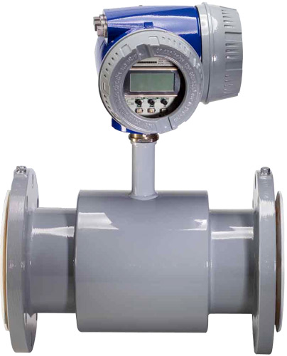
The diverse applications within the oil industry call for a wide range of metering technologies with Coriolis mass, ultrasonic and turbine meters finding widespread application. Production plant presents a complex environment for flow measurement, platform space will always be at a premium and many meters are installed in situations that are far from ideal. Some of the typical oil and gas applications include- fluid loss and leak detection; process gas flow; cooling water flow monitoring; hydraulic fluid flow sensing in blow-out prevention; fiscal or custody transfer metering; measuring produced water discharge.

Things to Keep in Mind While Selecting Oil Flow Meters

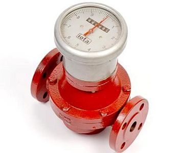
In general, it is a bad idea to select an oil flow meter on the basis of line size. From practical experience we know that there are specific applications where the existing lines are frequently oversized. Meters of the same line size can have widely different flow ranges. This is frequently seen on small oil meters used for burner service. A magnetic or ultrasonic flow meter should be used if you have fibers, silt, and bits of matter coming from a cleaning process, biological matter or anything that can get into the bearings.

Basic Principles and Advantages entailed – Magnetic Flow Meters


When a flowing conducting fluid is subjected to a diagonally magnetic field, the flowing conducting fluid cuts the magnetic field and sources a voltage to be stimulated. This induced voltage is comparative to the liquid swiftness, i.e., flow rate.

Construction

A conducting fluid is flowing through a non-magnetic and non-conducting pipe, that flow rate is to be calculated. Two electrodes are linked in opposite sides of pipe carrying the conducting fluid. These electrodes get in touch with flowing conducting fluid. The pipe is surrounded by an electromagnet that creates a magnetic field.

Benefits

These Magnetic Flow Meters does not cause barrier to flow and hence cause no drop in pressure. For ability, it does not matter if the flow is laminar or turbulent. It gives exact results. Its constancy is high, i.e., it gives a standard performance for an extensive period of time. It can handle greasy materials and liquids comprising of suspended solids. The dimension is self-regulating of temperature, pressure, viscosity and density.

Magnetic Flow Meters

Working Principle

The theory of operation for the magnetic flow meter is based on the Faraday’s Law of Electromagnetic Induction.

When a conductive fluid flows through the magnetic field, a small voltage (u) is stimulated. This voltage is relative to the speed of the flow and is precisely measured by two stainless steel electrodes mounted opposite each other inside the metering pipe. The two electrodes are linked to an advanced electronic input circuitry that processes the signal and in turn feeds it to the microprocessor inside the electronics module. The microprocessor then computes the volumetric flow and directs the various outputs on the terminal board.